
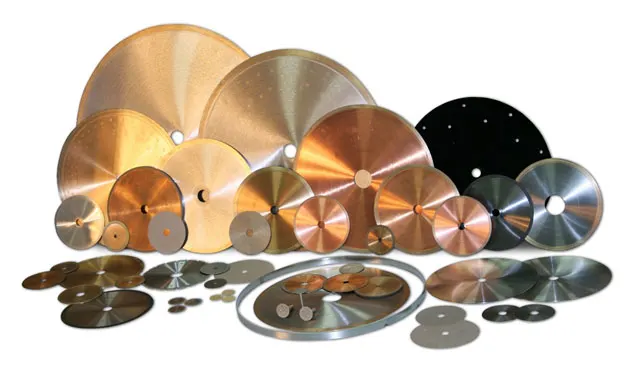
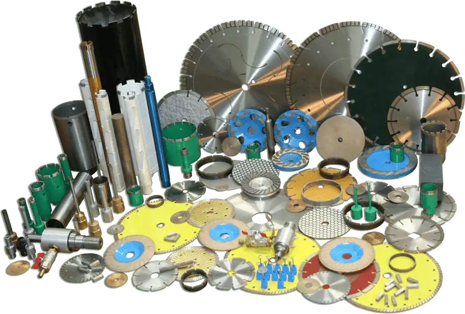


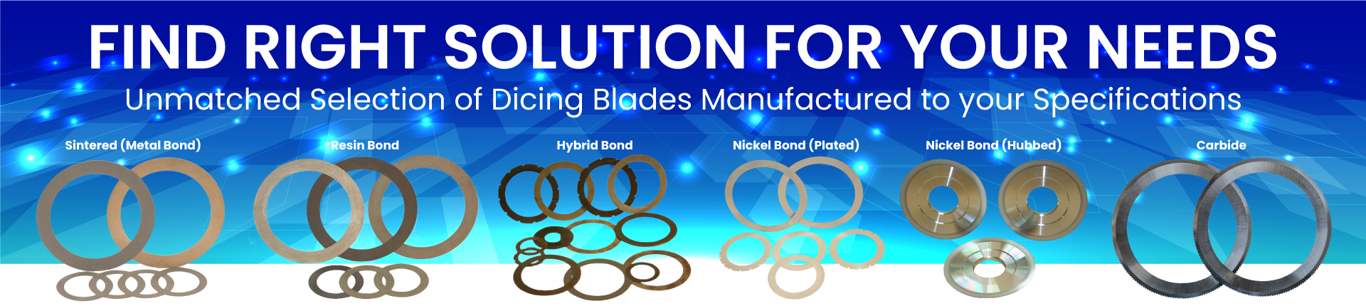
Select right Diamond Dicing Blade for your application


|
DICING BLADE BOND TYPES |
RESIN |
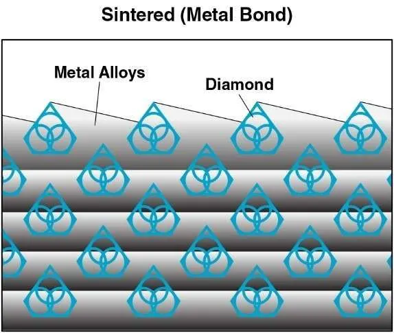
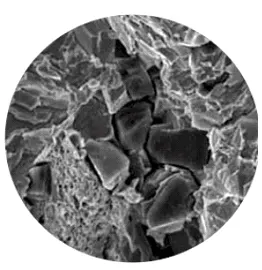
SINTERED (METAL BOND) |
HYBRID BONDTM |
NICKEL BOND (HUBLESS) |
NICKEL BOND (HUBBED) |
|---|---|---|---|---|---|
|
|
|
|
|
|
|
|
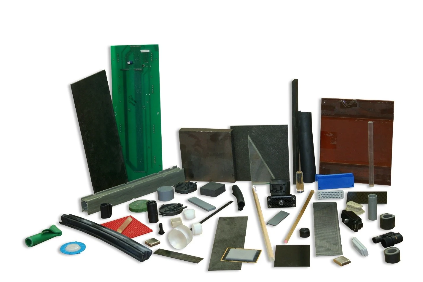
DICING BLADE APPLICATIONS |
|
|
|
|
|
|
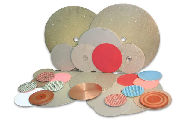
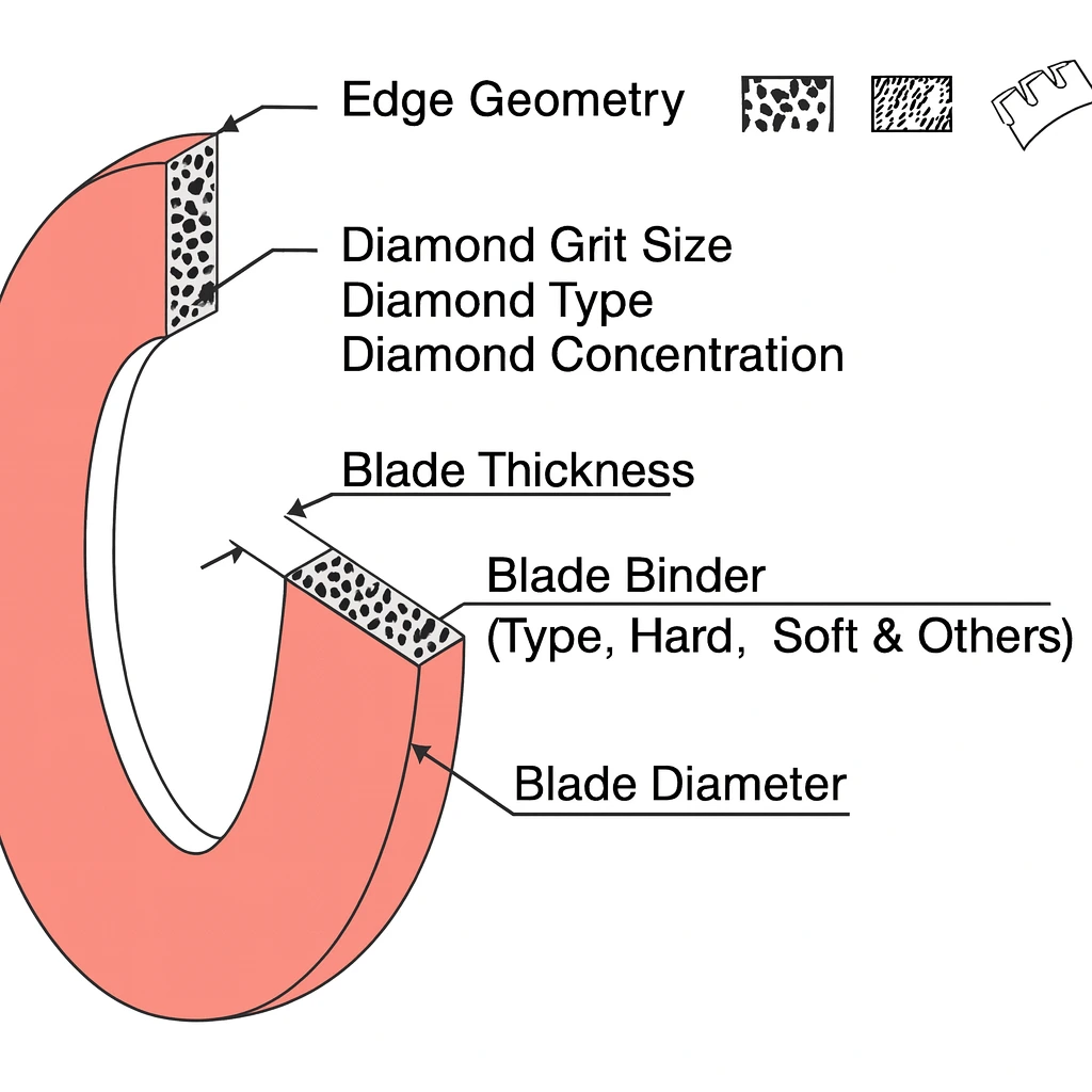
Dicing Blade Characteristics |
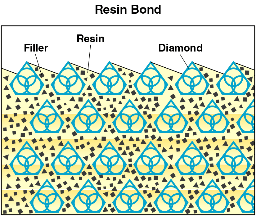
Resin Bond dicing blade are typically more forgiving. self dressing, and freer cutting. Excellent choice for Ultra Hard & Brittle Materials. Recommended for applications where cut quality and surface finish is very important. |
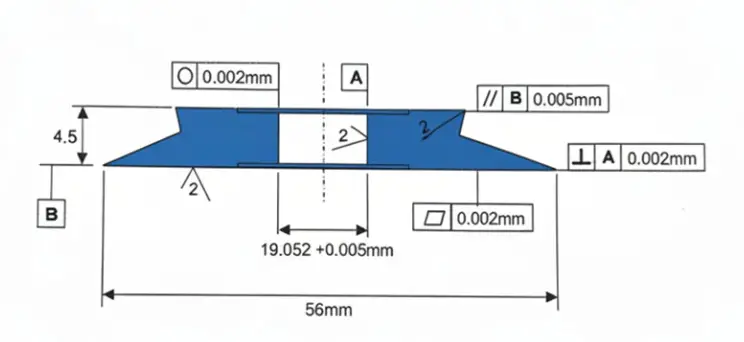
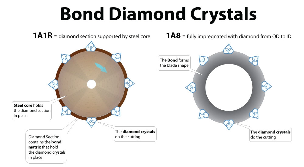
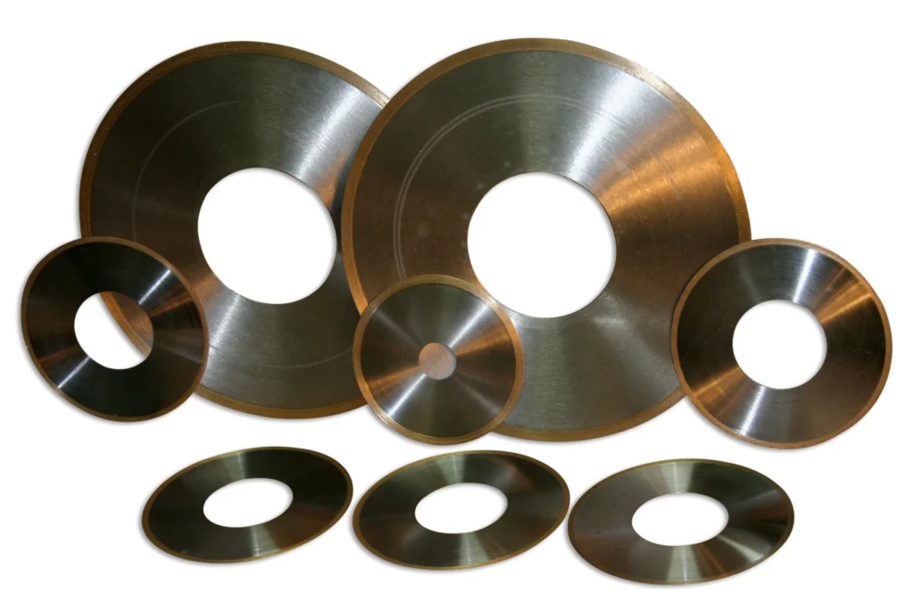
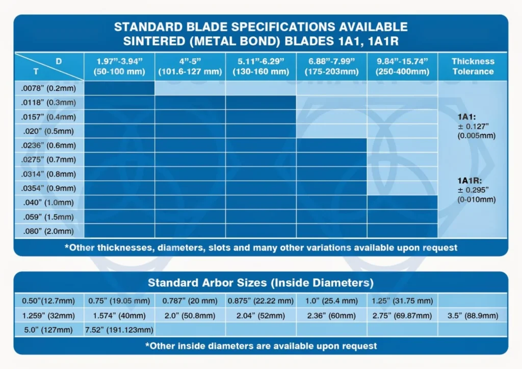
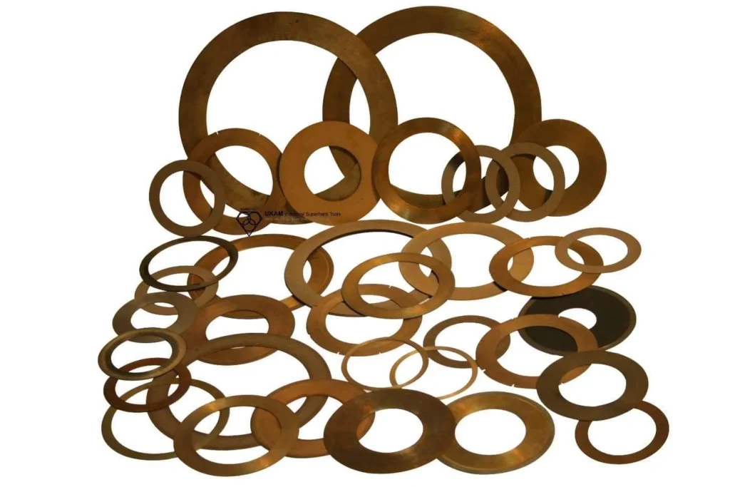
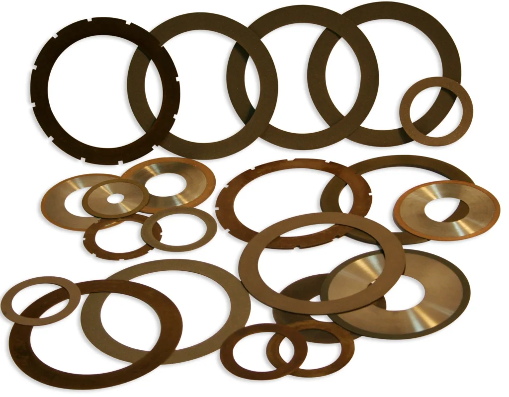
Sintered (metal bond) Dicing blades have excellent form holding & corner characteristics, provide very long life, high level of consistency. Recommended for users requiring very straight cuts and larger blade |
You will find all the advantages of cutting speed and fine finish that you have come to expect in a resin bond, and long life, consistency, aggressiveness, durability, and excellent performance on you look for in a metal bond. |
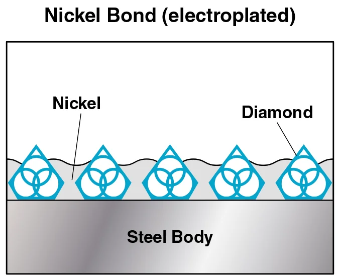
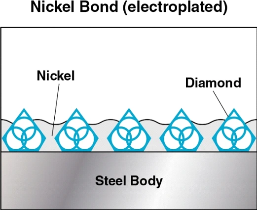
Nickel Bond dicing blades are available with and without hubs. Capable of maintaining excellent form & sharpness. Widely used for cutting wafers and thin substrates. Nickel Bond dicing blades provide minimum level of chipping on wide variety materials. |
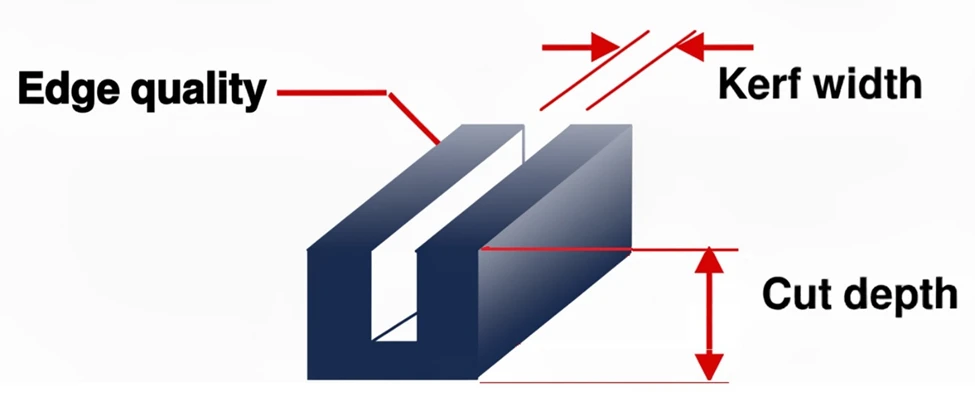
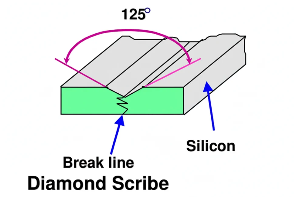
Nickel Bond Hubbed dicing blades are typically used for dicing silicon and III-V materials. Creates very thin kerfs, <50 microns. Providing excellent cut quality with low wear rate |
|
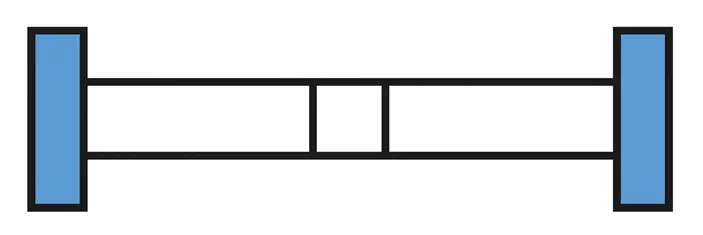
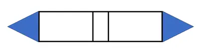
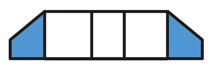
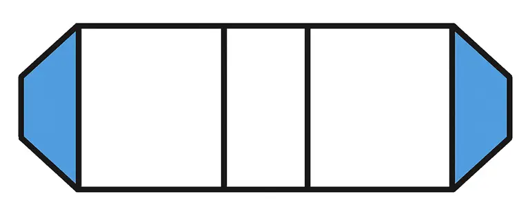
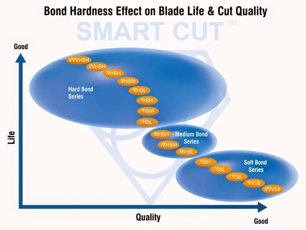
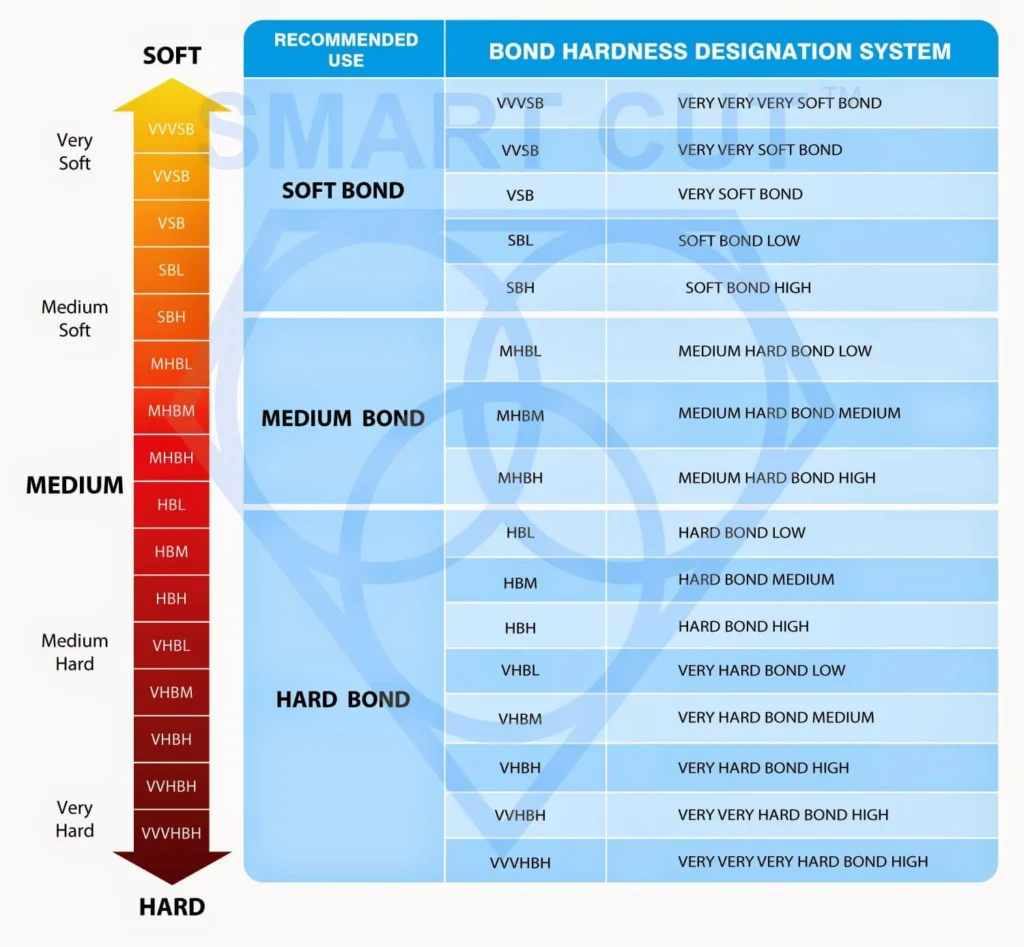
DICING BLADE BONDS |
|
|
|
|
|
|
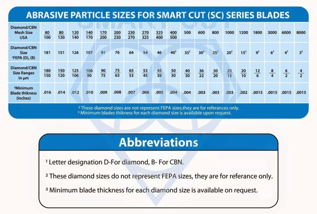
Abrasive (Diamond/CBN) Sizes |
3 to 151 micron |
3 to 126 micron |
3 to 151 micron |
3 to 70 micron |
2 to 50 micron |
|
Abrasive (Diamond/CBN) Types |
Coated & Uncoated Synthetic Diamond or CBN |
Natural Diamond, Coated & |
Coated & Uncoated Synthetic Diamond or CBN |
Natural & Synthetic Diamond |
Natural & Synthetic Diamond |
|
Abrasive Concentration |
25 to 200 con |
25 to 200 con |
25 to 200 con |
100 to 250 con |
100 to 250 con |
|
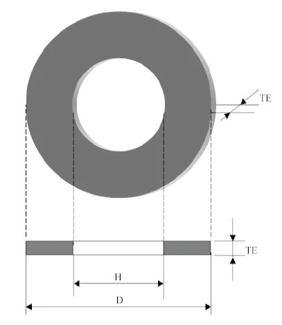
Minimum Dicing Blade Thickness |
.003" (.076mm) |
.004" (0.101mm) |
.004" (0.101mm) |
0003" (0.0076mm) |
.0003" (0.0076mm) |


-
 BGA Packages
-
QFN
-
Aluminum oxide (Al₂O₃)
-
Silicon nitride (Si₃N₄)
-
Silicon carbide (SiC)
-
Sapphire Boron Carbide (B₄C)
-
Alsmag
-
LiTaO₃ & LiNbO
-
FR4 and Resin


-
Green ceramics
-
Printed Circuit Board (PCB) substrates
-
Fiberglass
-
Laminates
-
Molded Lead Frame Packages (MLP)/Quad Flat No-leads (QFN)
-
Graphite
-
Plastics
-
Rubber
-
Wood and MDF
-
Carbon Fiber
-
Aluminum Foils
-
Copper and Brass Sheets
-
Copper
-
Aluminum
-
Stainless steel
-
Resin
-
Titanium alloy
-
Low carbon steel
-
Medium carbon steel


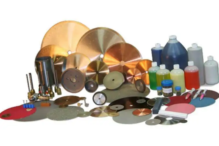
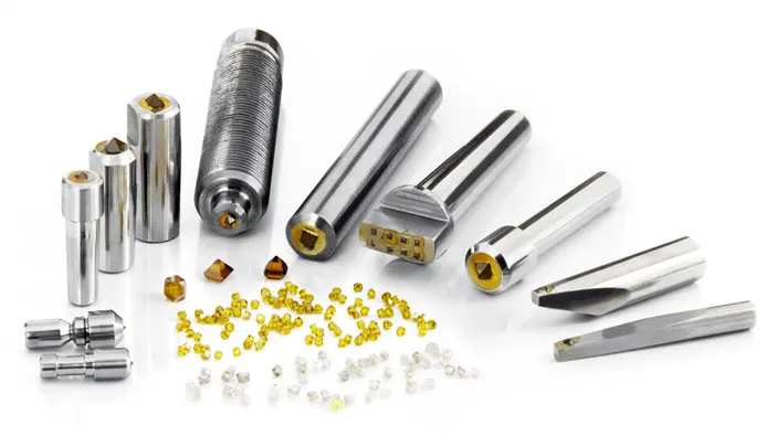
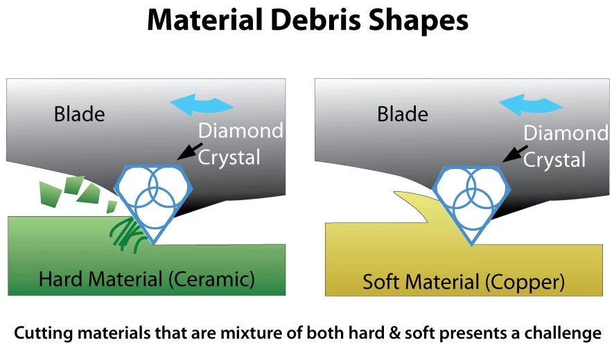
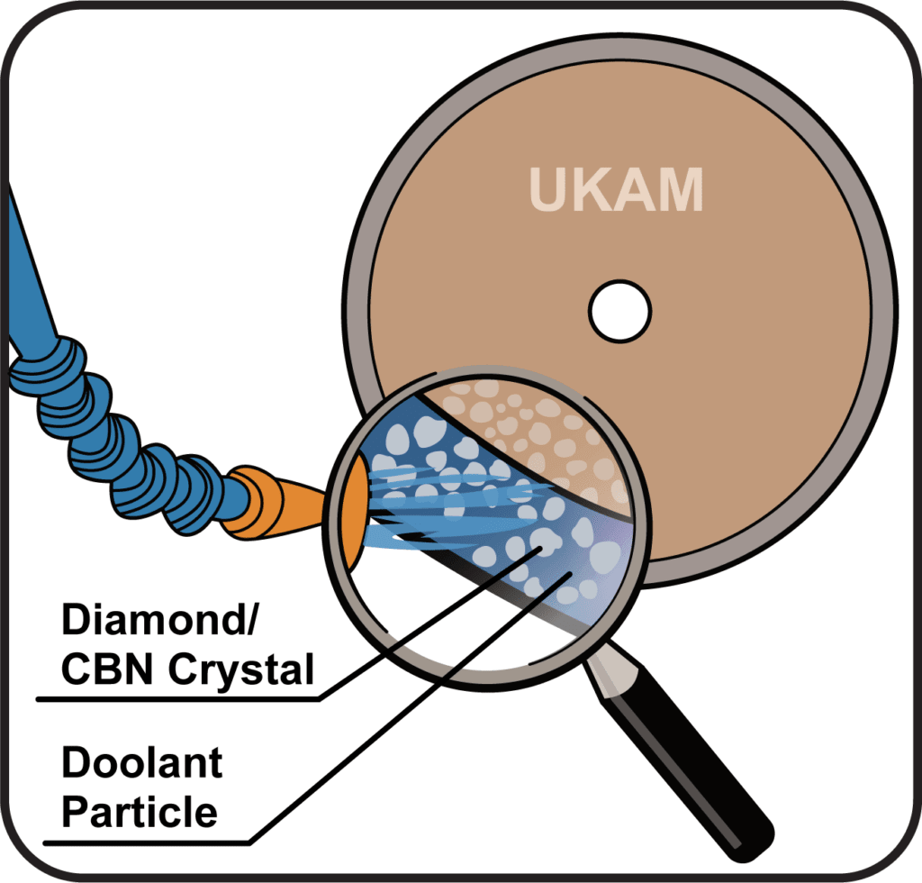
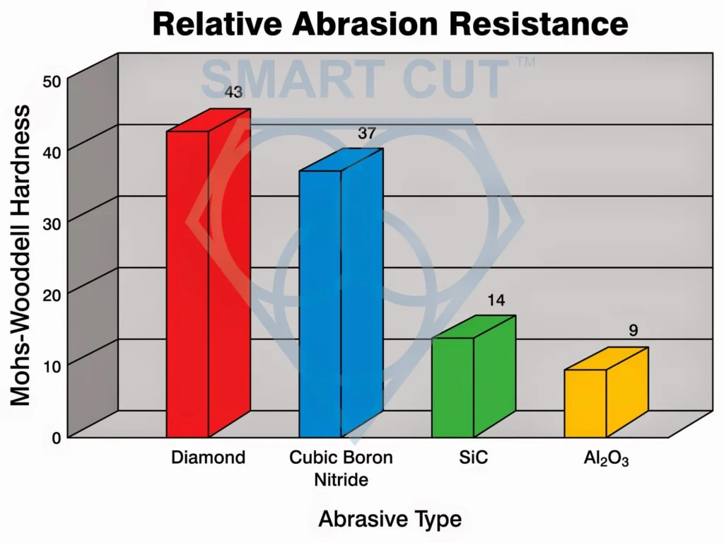
In dicing applications, diamond and CBN together provide complete coverage. Diamond excels in cutting brittle, non-ferrous, and crystalline materials with unmatched precision, while CBN enables the machining of ferrous alloys and superalloys that diamond cannot process. By selecting the right abrasive, bond type, and blade geometry, operators can achieve optimal cut quality, blade life, and cost efficiency for their specific materials.


Leon Meyer is a veteran manufacturing engineer and technical consultant with over 50 years of experience in the development, implementation, and troubleshooting of industrial diamond tooling systems. Having spent his career at the intersection of tool design, precision manufacturing, and production engineering, Mr. Meyer is widely regarded as one of the most experienced voices in the application of ultra-thin diamond blades, sintered core drills, and CBN grinding wheels across heavy industry, advanced materials, and research sectors.
Known for his pragmatic, no-nonsense approach, Leon has advised manufacturers across the United States, Europe, and East Asia—helping streamline cutting processes, extend tool life, and solve complex issues related to material breakage, chipping, and tolerance drift. His expertise has directly contributed to improved production efficiency in industries ranging from aerospace alloys and technical ceramics to optics, composites, and high-nickel superalloys.
As an author, Mr. Meyer brings a lifetime of field knowledge to his writing, with a focus on real-world problem solving, cost-performance optimization, and tool reliability under demanding conditions.
Select right Diamond Dicing Blade for your application

Dicing Blade Operations Recommendations
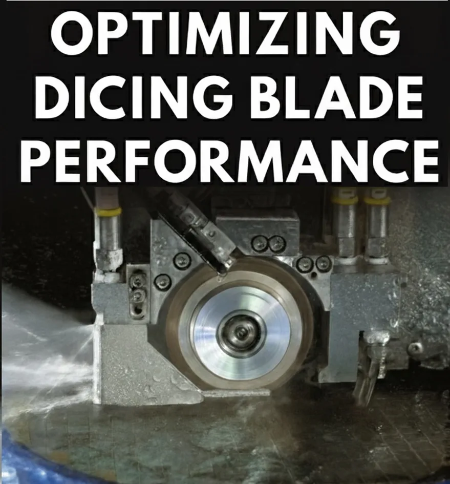
Optimizing your Diamond Dicing Performance

Trouble Shooting Dicing Problems

Application Recommendations

Dicing Blade Case Studies
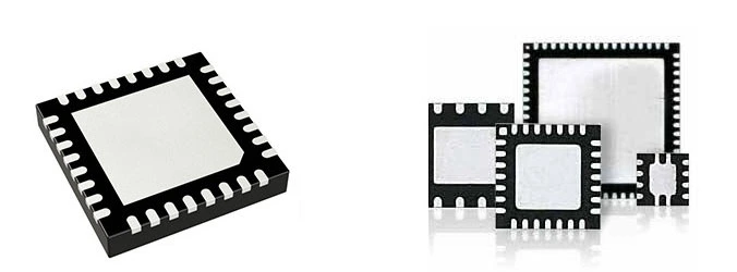
Optimizing QFN Package Dicing Process Using SMART CUT® Dicing Blades
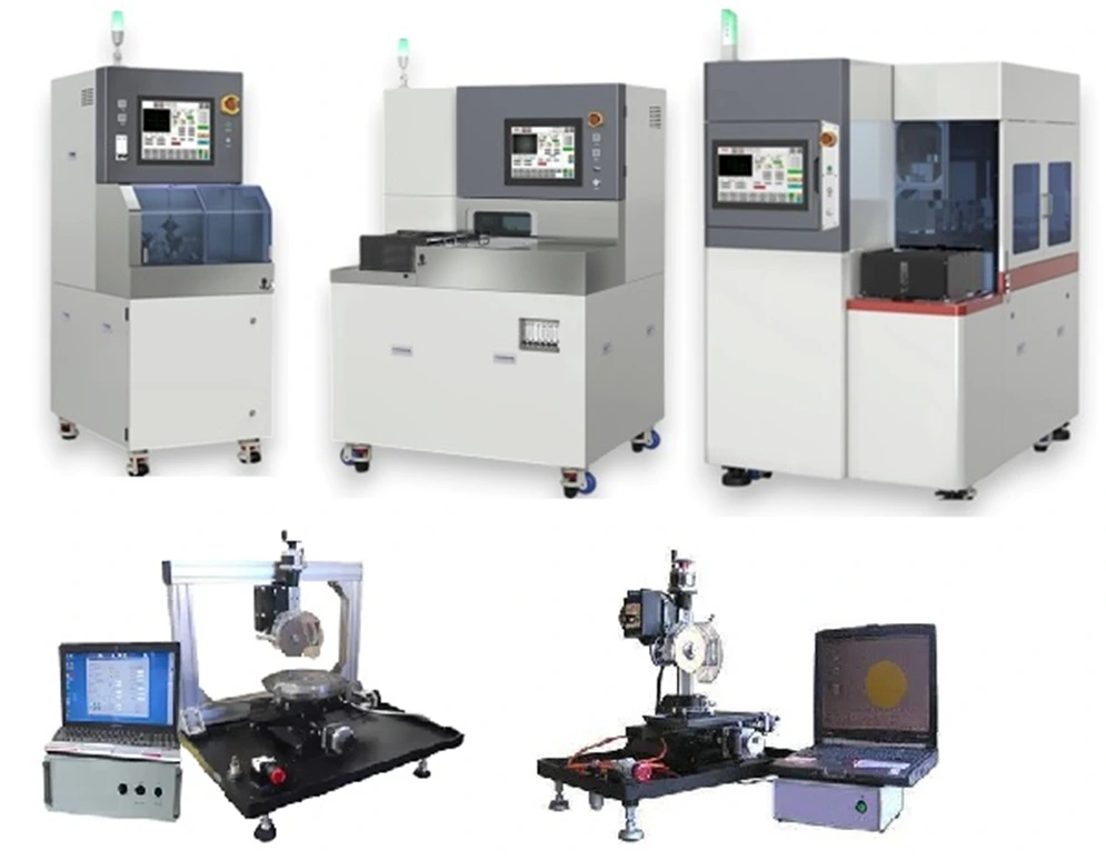
Selecting the Right Wafer Dicing Saw Practical Guide
Practical Guide to Semiconductor Wafer Dicing: Materials, Blades, and Process Optimization

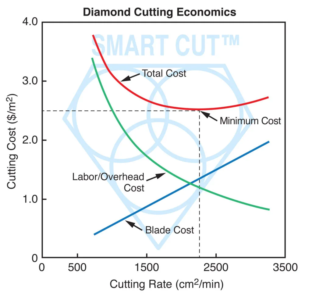
Total Cost of Ownership – Measuring the Real Economics of Diamond Dicing
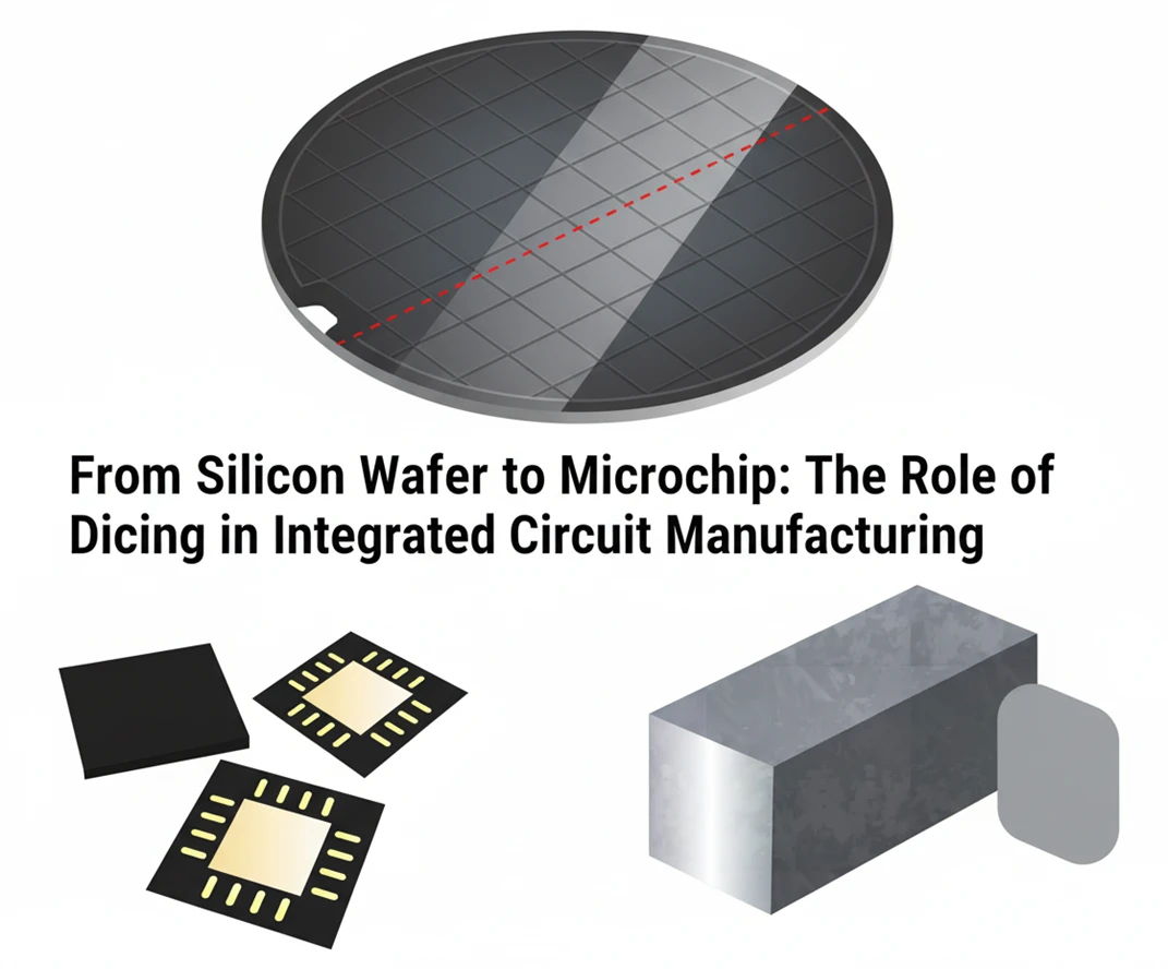
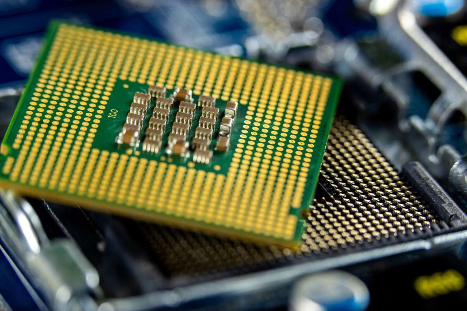
From Silicon Wafer to Microchip: The Role of Dicing in Integrated Circuit Manufacturing
Improving Diamond Dicing Blade Performance: Key Factors and Strategies

How to Selecting Right Diamond Tools for your application

How to properly use Diamond Tools

Why use diamond
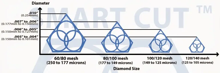
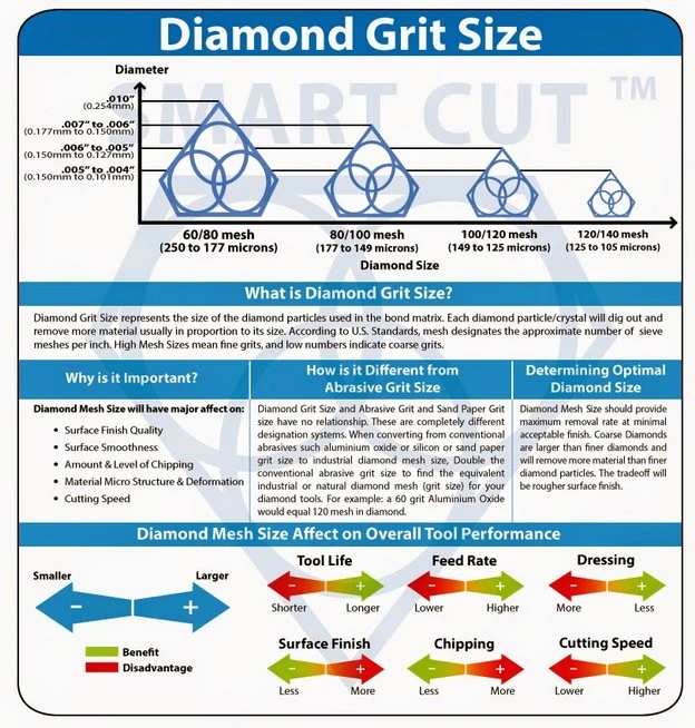
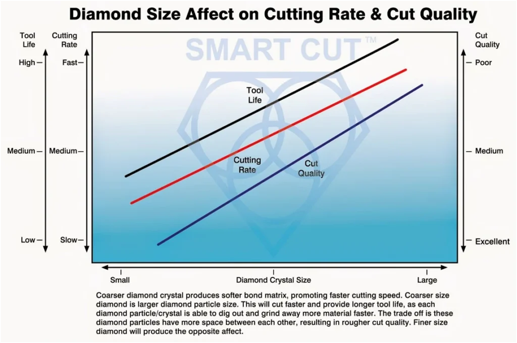
What is Diamond Mesh Size and how to select best one for your application

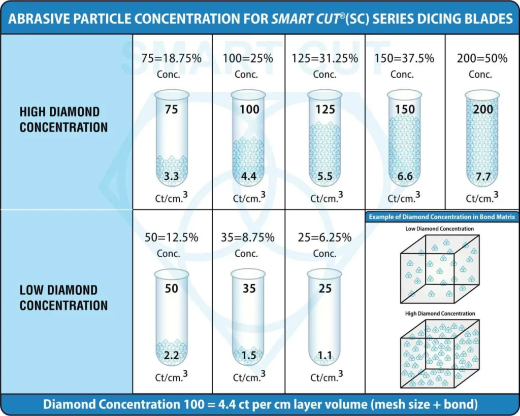
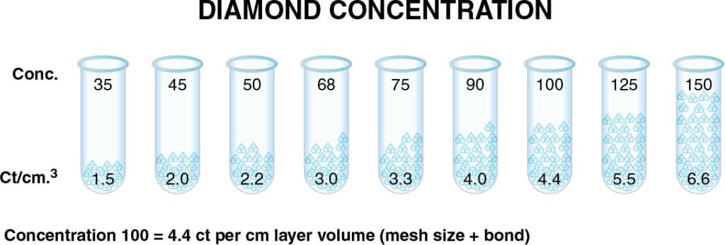
What is Diamond Concentration and which to use for your application

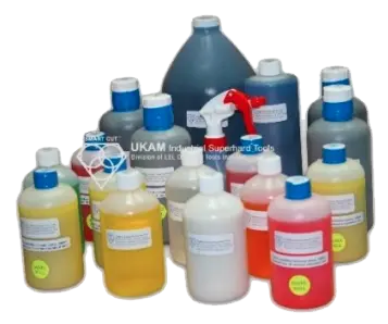
Diamond Tool Coolants Why, How, When & Where to Use
Diamond vs CBN (cubic boron nitride) Tools

Choosing The Correct Diamond Bond Type
Leon Meyer is a veteran manufacturing engineer and technical consultant with over 50 years of experience in the development, implementation, and troubleshooting of industrial diamond tooling systems. Having spent his career at the intersection of tool design, precision manufacturing, and production engineering, Mr. Meyer is widely regarded as one of the most experienced voices in the application of ultra-thin diamond blades, sintered core drills, and CBN grinding wheels across heavy industry, advanced materials, and research sectors.
Known for his pragmatic, no-nonsense approach, Leon has advised manufacturers across the United States, Europe, and East Asia—helping streamline cutting processes, extend tool life, and solve complex issues related to material breakage, chipping, and tolerance drift. His expertise has directly contributed to improved production efficiency in industries ranging from aerospace alloys and technical ceramics to optics, composites, and high-nickel superalloys.
As an author, Mr. Meyer brings a lifetime of field knowledge to his writing, with a focus on real-world problem solving, cost-performance optimization, and tool reliability under demanding conditions.