


Dicing Blade Operations Recommendations

-
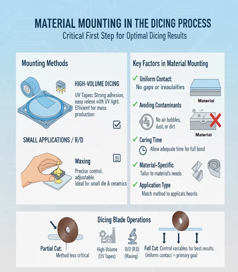
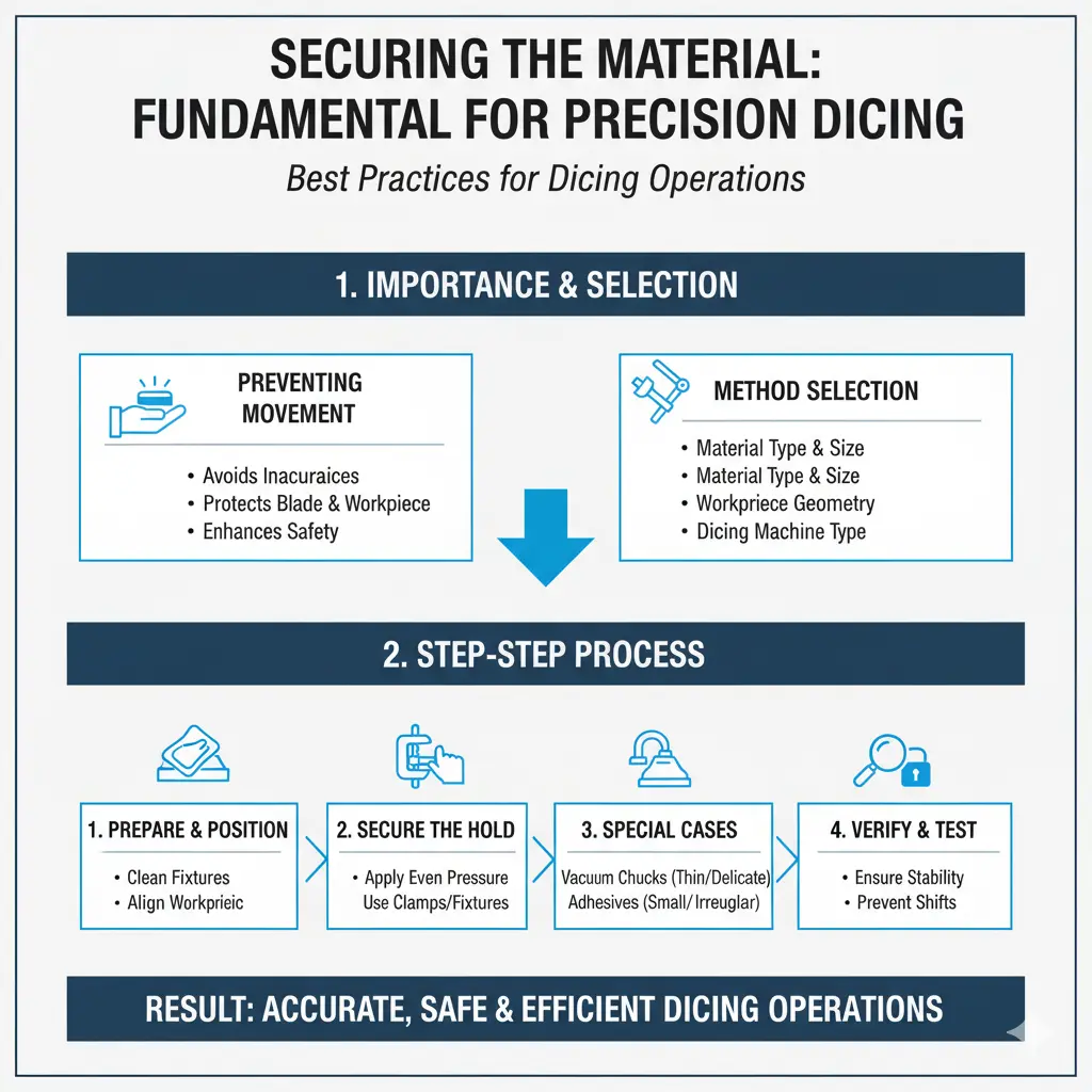
 1. Uniform Contact: Ensuring uniform contact between the material and the tape is critical. Any gaps or irregularities can cause instability during the dicing process, leading to inaccurate cuts or damage to the material.
-
2. Avoiding Contaminants: It is vital to avoid air bubbles, dust, and dirt particles between the material and the mounting media. These contaminants can create weak points or irregularities in the mounting, affecting the dicing accuracy and quality.
-
3. Curing Time: For methods like UV tapes or waxing, allowing adequate curing time is essential. This ensures the adhesive or wax has fully bonded with the material, providing a stable and secure mount.
-
4. Material-Specific Considerations: Different materials may require different mounting methods. For instance, delicate or brittle materials might need a softer mounting media to prevent stress and damage during the dicing process.
-
5. Application Type: The choice of mounting method may vary based on the application type. High-volume production might prioritize speed and efficiency, using UV tapes, while R&D or custom applications might require the precision and adjustability of waxing.

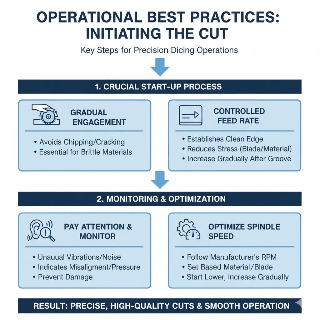
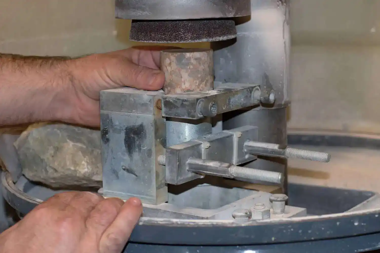
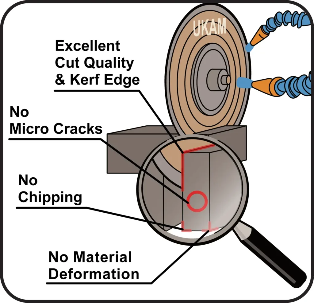
Perform a visual inspection of the initial cut to ensure it is clean and free of defects. Look for signs of chipping, cracking, or uneven edges, which can indicate improper setup or blade issues. Evaluate the quality of the cut by checking for burr formation or surface roughness. High-quality cuts should have minimal burrs and a smooth surface finish.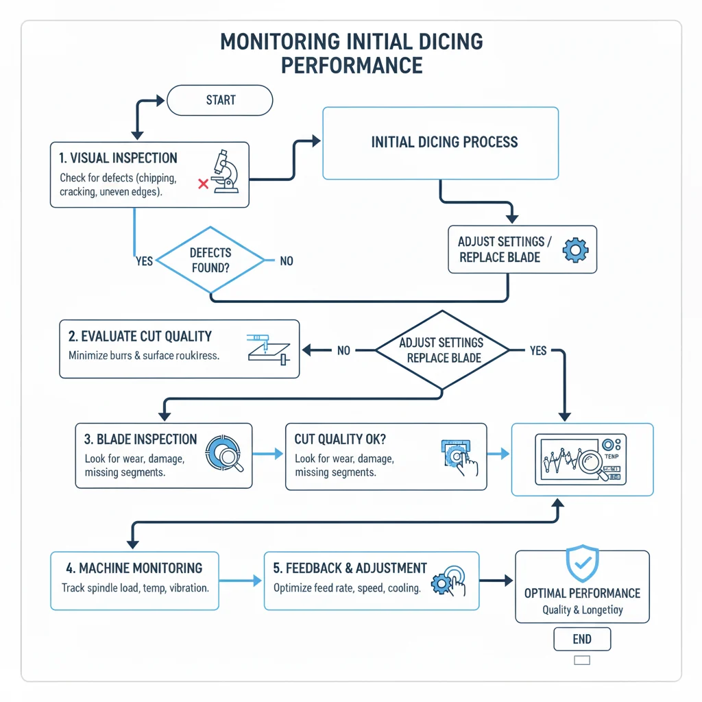
Regularly inspect the blade for signs of wear or damage during the initial stages of cutting. Any abnormalities, such as excessive wear, deformation, or missing segments, should be addressed immediately to prevent further issues. Utilize any available machine monitoring systems to track parameters such as spindle load, temperature, and vibration. Real-time data can provide valuable insights into the cutting process and help in making necessary adjustments.
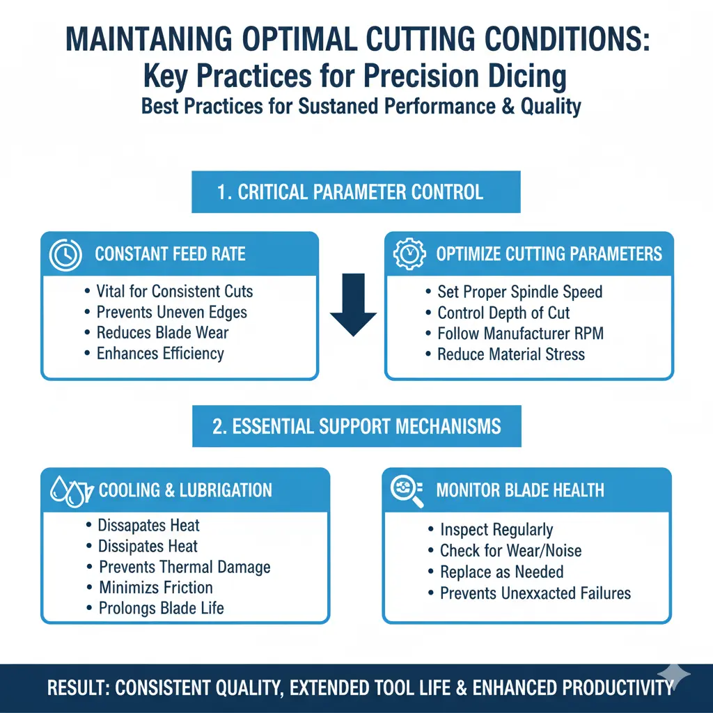
Establish a feedback loop to continuously monitor and adjust cutting parameters. This includes making incremental changes to feed rate, spindle speed, and cooling to optimize performance based on the initial observations. By following these best practices for starting the cut and monitoring initial performance, users can ensure a smooth and efficient cutting process, leading to superior quality and longevity of both the diamond dicing blade and the workpiece.

-
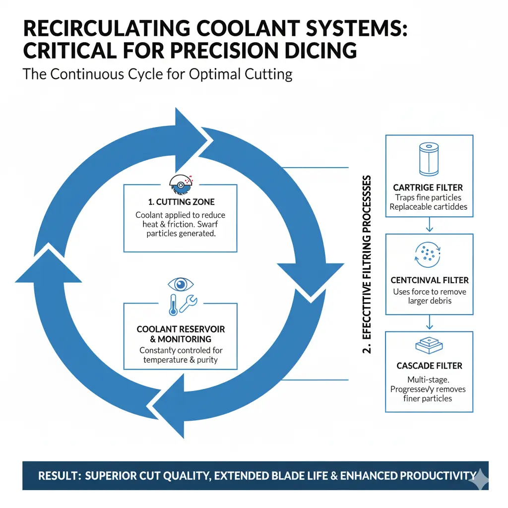
Cartridge filters: These filters trap swarf particles as coolant passes through replaceable cartridges. They are suitable for applications requiring fine filtration and are relatively easy to maintain.
-
Centrifugal filters: These systems use centrifugal force to separate swarf particles from the coolant. They are effective for removing larger particles and are ideal for applications with high volumes of debris.
-
Cascade filters: This method involves a series of filtration stages, progressively removing finer particles at each stage. Cascade filters are highly effective for ensuring a high level of coolant purity.
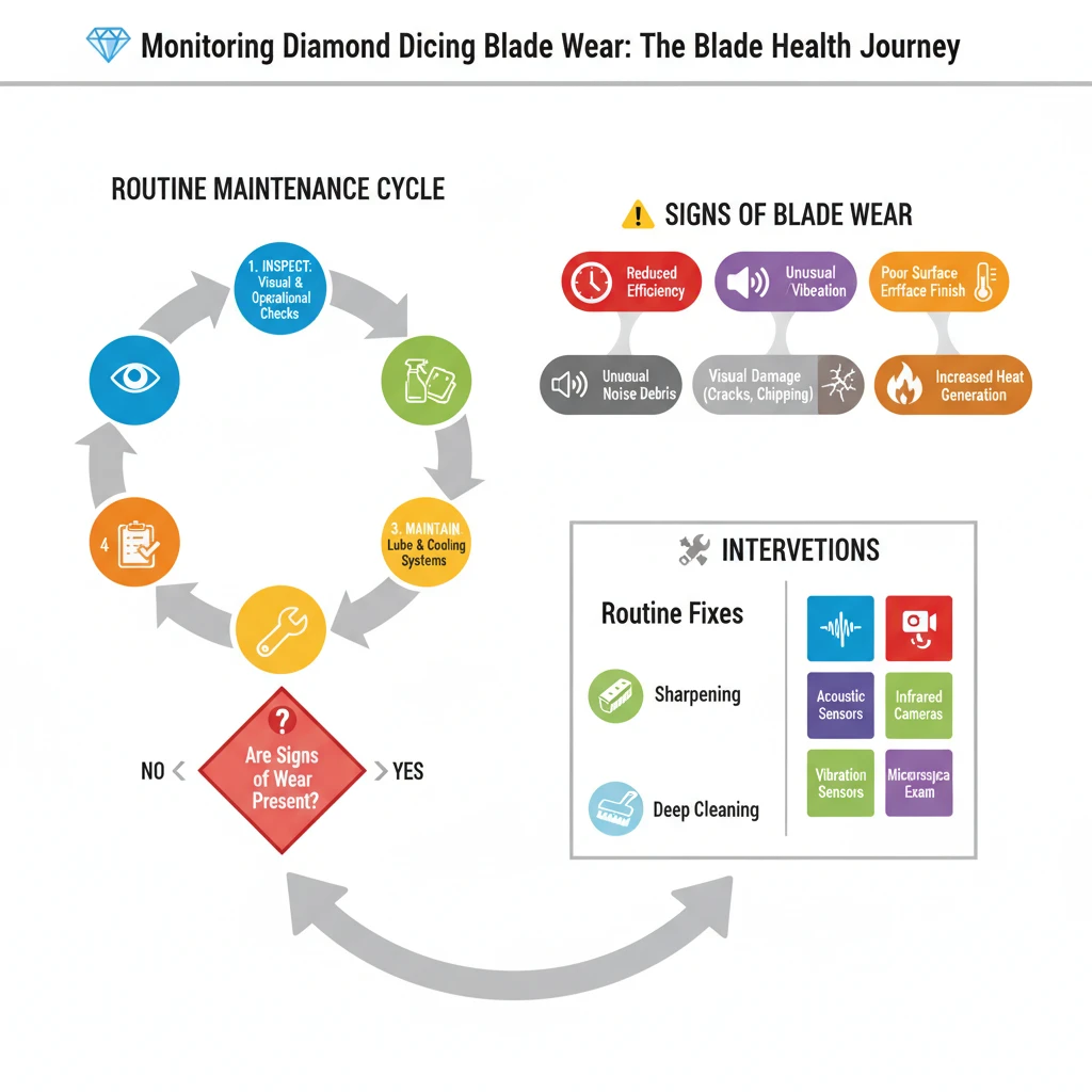 Keep track of cutting parameters such as spindle speed, feed rate, and coolant flow. Consistent monitoring helps in identifying any deviations that could indicate blade wear or other issues. Depending on the blade type and material being cut, periodic sharpening may be necessary. Follow the manufacturer’s guidelines for sharpening to restore the blade’s cutting edge. Maintain detailed records of blade usage, maintenance activities, and any issues encountered to help track the blade’s performance over time and predict when maintenance or replacement is needed.
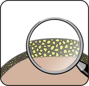
For more precise monitoring, advanced techniques can be employed. Acoustic emission sensors can detect sound waves generated by blade wear, providing real-time data on blade condition and helping in early detection of wear. Infrared cameras can be used to monitor the temperature of the blade and the workpiece during cutting, with abnormal temperature patterns indicating wear or other issues. Vibration sensors can monitor the vibration levels during cutting, as changes in vibration patterns can be indicative of blade wear or machine misalignment. Periodically examining the blade under a microscope can detect micro-level wear and damage that may not be visible to the naked eye.
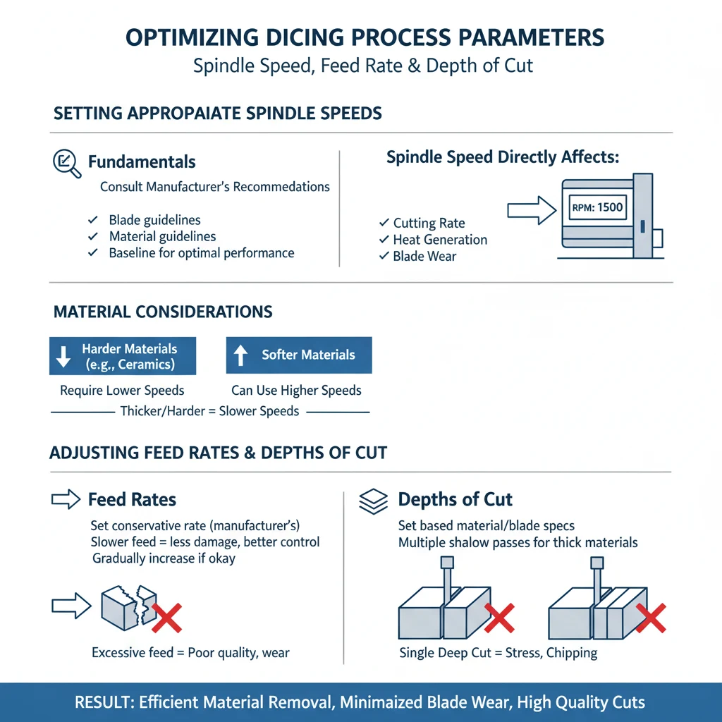
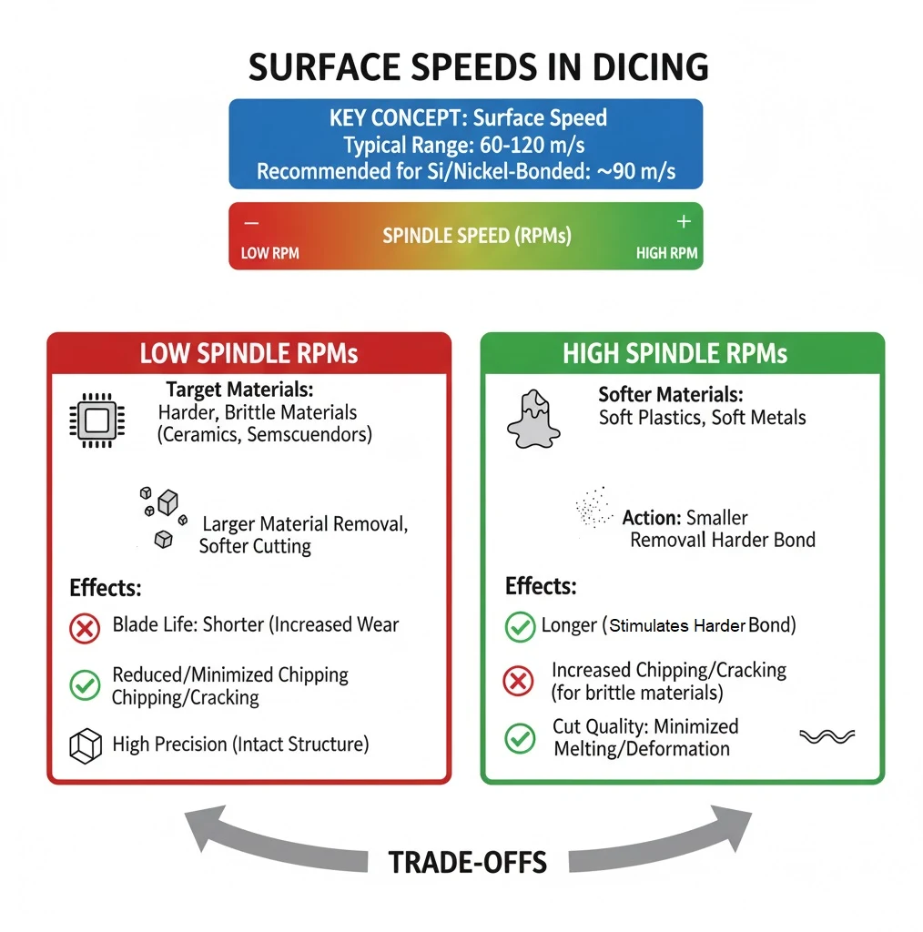
Typical surface speeds in dicing applications range from 60 to 120 meters per second (m/s). For nickel-bonded blades on silicon, a surface speed of approximately 90 m/s is recommended. When using resin-bonded dicing blades, altering the surface speed can influence blade behavior. If the chuck speed is kept constant, increasing the rotational speed will simulate the effects of using a harder bond, resulting in longer blade life but more chipping. Conversely, reducing the rotational speed will soften the cutting action, potentially reducing chipping but also shortening blade life.
The desired cut quality is a primary consideration when setting the feed rate. Higher feed rates can increase cutting speed and output but often at the expense of cut quality. This trade-off must be carefully managed to ensure that the final product meets the required specifications. The feed rate must be balanced to avoid excessive chipping and material cracking, which can increase die rejection rates and compromise the integrity of the cut.
Material hardness and density are also key factors in determining the feed rate. Harder and denser materials require slower feed rates to ensure that the blade can effectively cut through the material without causing damage. For example, cutting materials such as silicon wafers or advanced ceramics typically necessitates a slower feed rate to prevent chipping and ensure a smooth cut. In contrast, softer materials like certain plastics or soft metals may tolerate higher feed rates, allowing for faster cutting without compromising quality.
Material thickness also influences the appropriate feed rate. Thicker materials generally require slower feed rates to maintain control and precision during the cutting process. Thinner materials may allow for faster feed rates, but careful monitoring is still essential to prevent deformation or damage.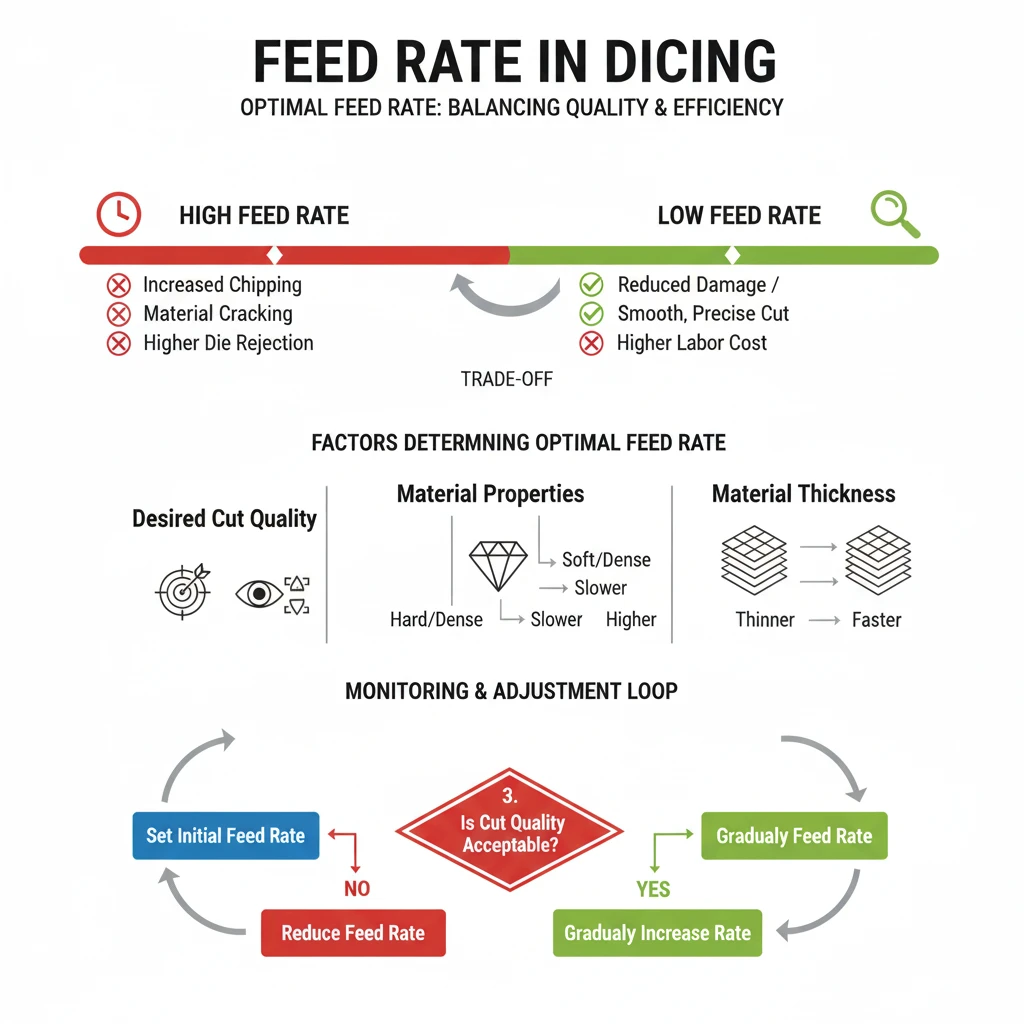
-
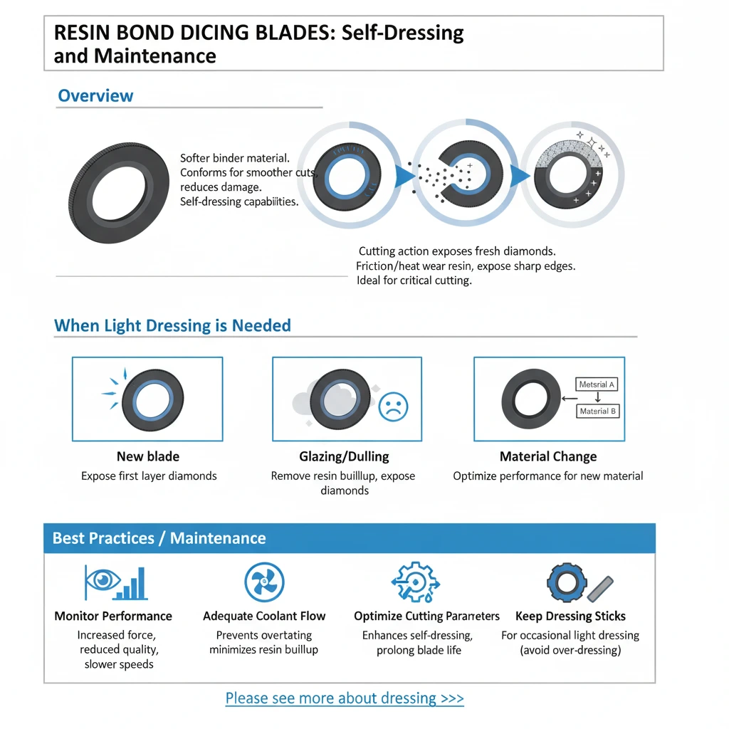
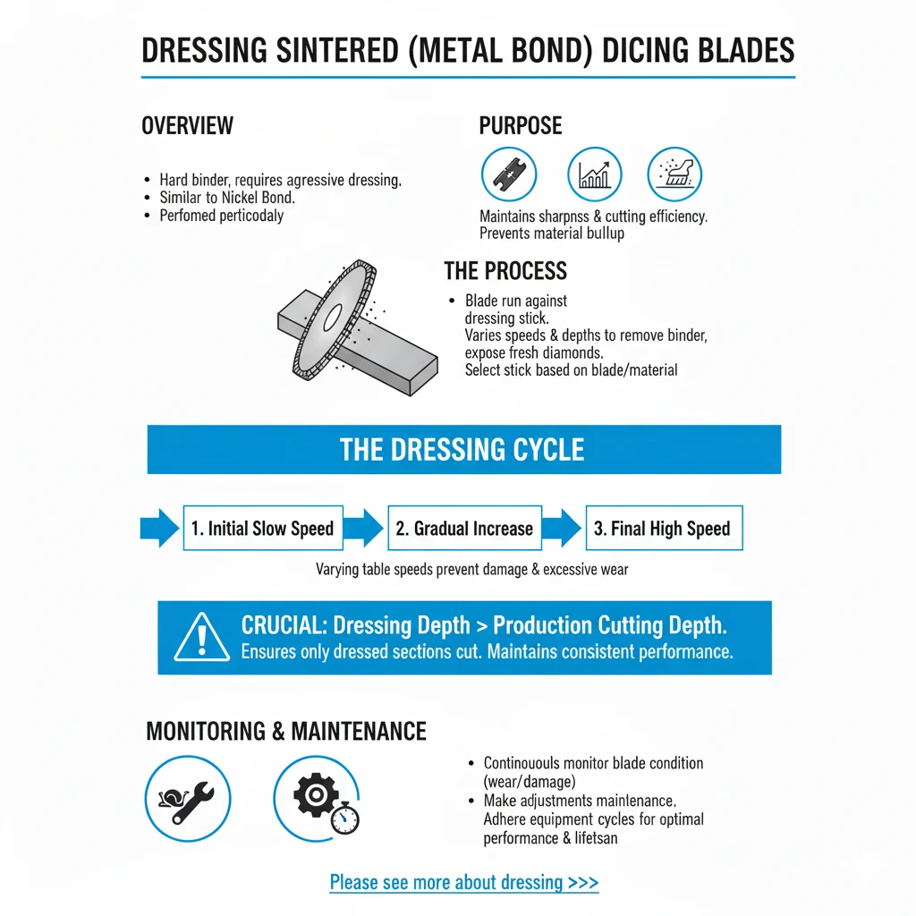
Initial Slow Speed: Start the dressing process at a slow table speed to gently begin the removal of built-up material.
-
Gradual Increase: Gradually increase the table speed to progressively remove more material and evenly dress the blade surface.
-
Final High Speed: Reach near production speed towards the end of the cycle to ensure the blade is conditioned for high-speed cutting.
-
Depth Adjustment: Ensure that the dressing depth exceeds the production cutting depth to use only dressed sections of the blade for actual cutting operations.
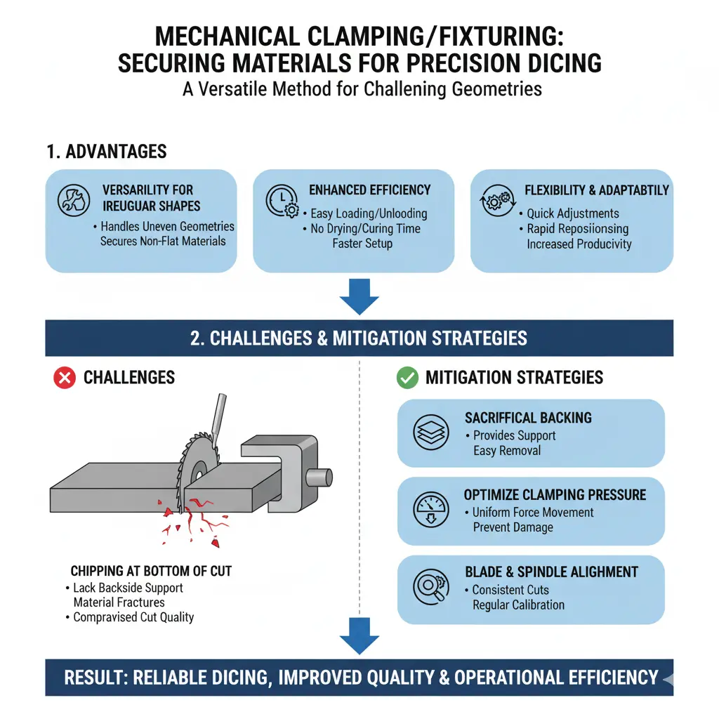
When dicing materials with significant thickness, several challenges need to be addressed to ensure precise cuts and optimal blade performance. These challenges include selecting the appropriate blade thickness and exposure, considering the use of multiple passes, and mitigating backside chipping.
When dicing materials with a thickness of 1/4 inch, typically a 3 or 4-inch diameter blade is required. The blade thickness must be relative to the material thickness to accommodate the spindle load generated during cutting. For materials of this thickness, a blade thickness of .020 to .030 inches is recommended. This ensures the blade is robust enough to handle the load without excessive deflection or breakage. Two primary techniques for dicing thick materials can yield different results: the single pass technique and the multiple pass technique. The single pass technique utilizes a blade with the full required exposure, making a single pass through the material. This technique is generally faster but can lead to increased blade deviation and reduced cut quality, especially at the initial stages of cutting due to the lack of support. The multiple pass technique involves gradually cutting through the material in several passes. Recommended for materials thicker than .060 inches, this method reduces the load on the blade and spindle, providing more control and precision. Drawbacks include increased processing time, as each cut must be multiplied by the number of passes. Additionally, initial passes may suffer from blade deviation due to lack of support.
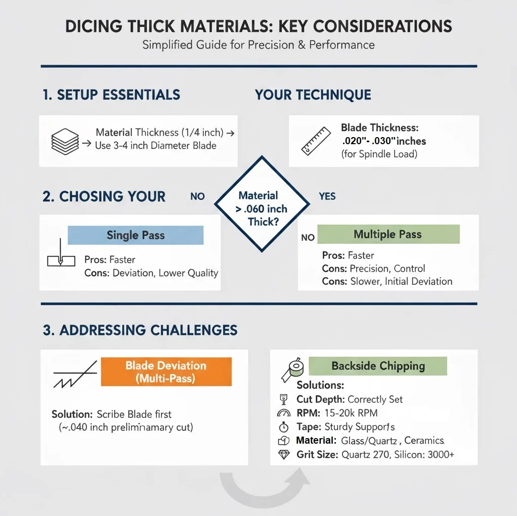
For materials with a thickness of .060 inches or greater, it is recommended to use the multiple pass technique. This involves making several passes with the blade, each removing a small amount of material until the entire thickness is cut through. For example, the first pass might cut .015 inches into the material, the second pass another .015 inches, and so on until the blade reaches beyond the tape and the cut is completed. To address the drawbacks of the multiple pass technique, blade deviation during initial passes can be mitigated by using a scribe blade with limited exposure. This blade makes a preliminary cut of about .040 inches, creating trenches for subsequent cuts. After scribing, switch to a blade with the full required exposure and complete the dicing in multiple passes over the pre-made trenches. The second blade tends to follow the scribe cuts, reducing waviness and improving cut accuracy.
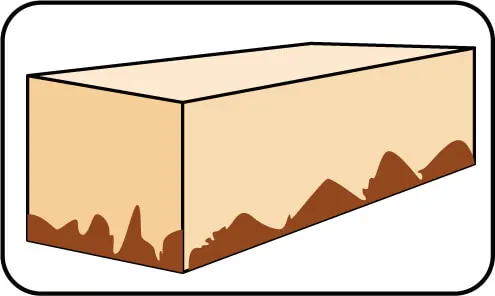
Backside chipping is a common issue during the final stages of cutting. It is caused by several factors, including improper cut depth, incorrect RPM or feed rate, and vibrations when the last segment of material is knocked off during the final pass. While there are no perfect solutions, the following measures can help mitigate this problem. Ensure that the cut depth is properly set to avoid excessive force on the material during the final pass. For 3 and 4-inch diameter blades, use an RPM of around 15,000. For 2-inch diameter blades, an RPM of 20,000 is recommended. Maintain a feed rate of approximately .02 inches per second, adjusting based on the material specifications and requirements. Use a sturdy tape that minimizes vibration, providing better support for the material during cutting. Select the appropriate grit size for the material being cut: for glass and quartz, use a 325 grit size; for ceramics, use a 270 grit size; for silicon, use a 3000 grit size or larger.

Alexander Schneider is a senior applications engineer and leading authority in the industrial diamond tooling industry, with over 35 years of hands-on experience in the development, application, and optimization of ultra-thin and high-precision diamond blades, diamond core drills, and diamond and CBN grinding wheels. His work spans a wide range of advanced materials including ceramics, glass, composites, semiconductors, and high-performance metals.
Throughout his career, he has collaborated with leading R&D institutions, national laboratories, and high-tech manufacturing companies across Europe, North America, and Asia, providing technical expertise and tailored solutions for demanding cutting and surface preparation applications.
Mr. Schneider has played a pivotal role in advancing precision cutting, sectioning, dicing, and grinding technologies used in research, production, and failure analysis. He is widely respected for his ability to optimize tool design and cutting parameters to meet exacting industry standards—balancing factors such as cut quality, blade life, material integrity, and process consistency.
As an author, Mr. Schneider is known for delivering practical, application-focused insights that translate complex technical challenges into clear, actionable strategies. His articles and technical guides serve as trusted resources for engineers, researchers, and manufacturers seeking to improve precision, reduce process variability, and enhance tool performance in critical applications.


Select right Diamond Dicing Blade for your application
Dicing Blade Operations Recommendations

Optimizing your Diamond Dicing Performance
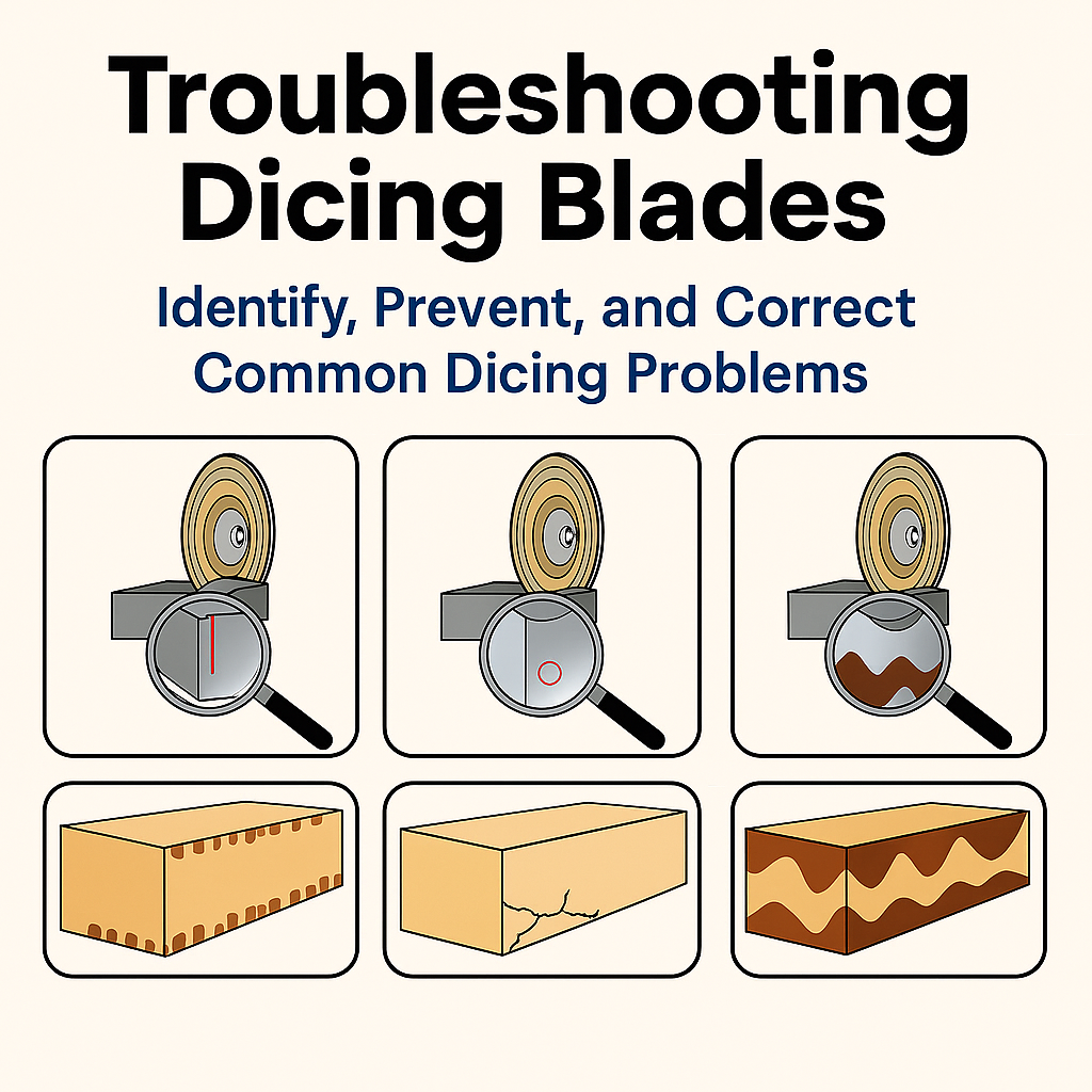
Trouble Shooting Dicing Problems
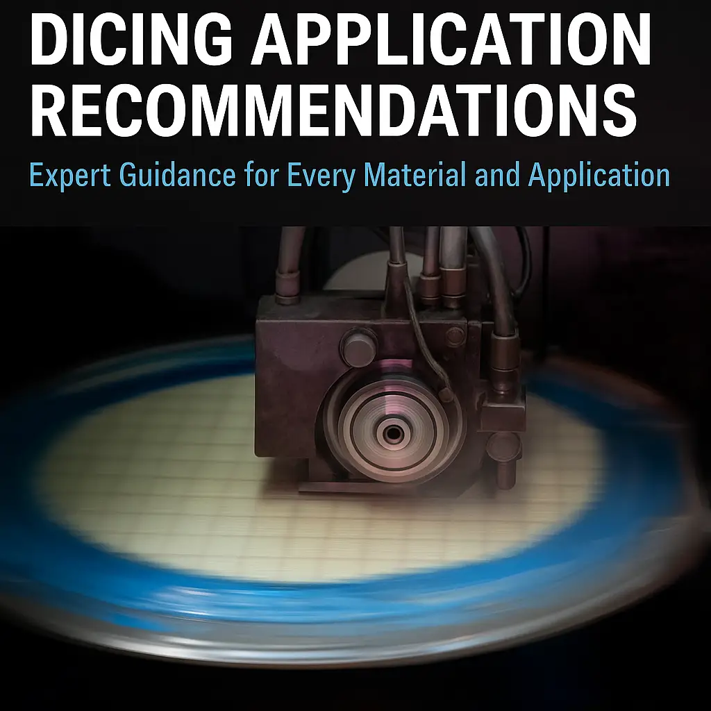
Application Recommendations
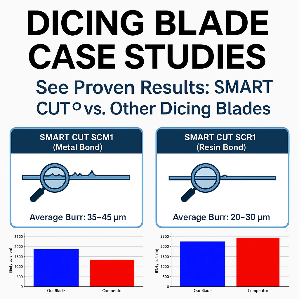
Dicing Blade Case Studies

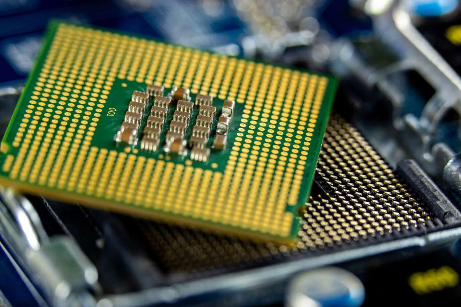
Optimizing QFN Package Dicing Process Using SMART CUT® Dicing Blades
Selecting the Right Wafer Dicing Saw Practical Guide
Practical Guide to Semiconductor Wafer Dicing: Materials, Blades, and Process Optimization

Total Cost of Ownership – Measuring the Real Economics of Diamond Dicing
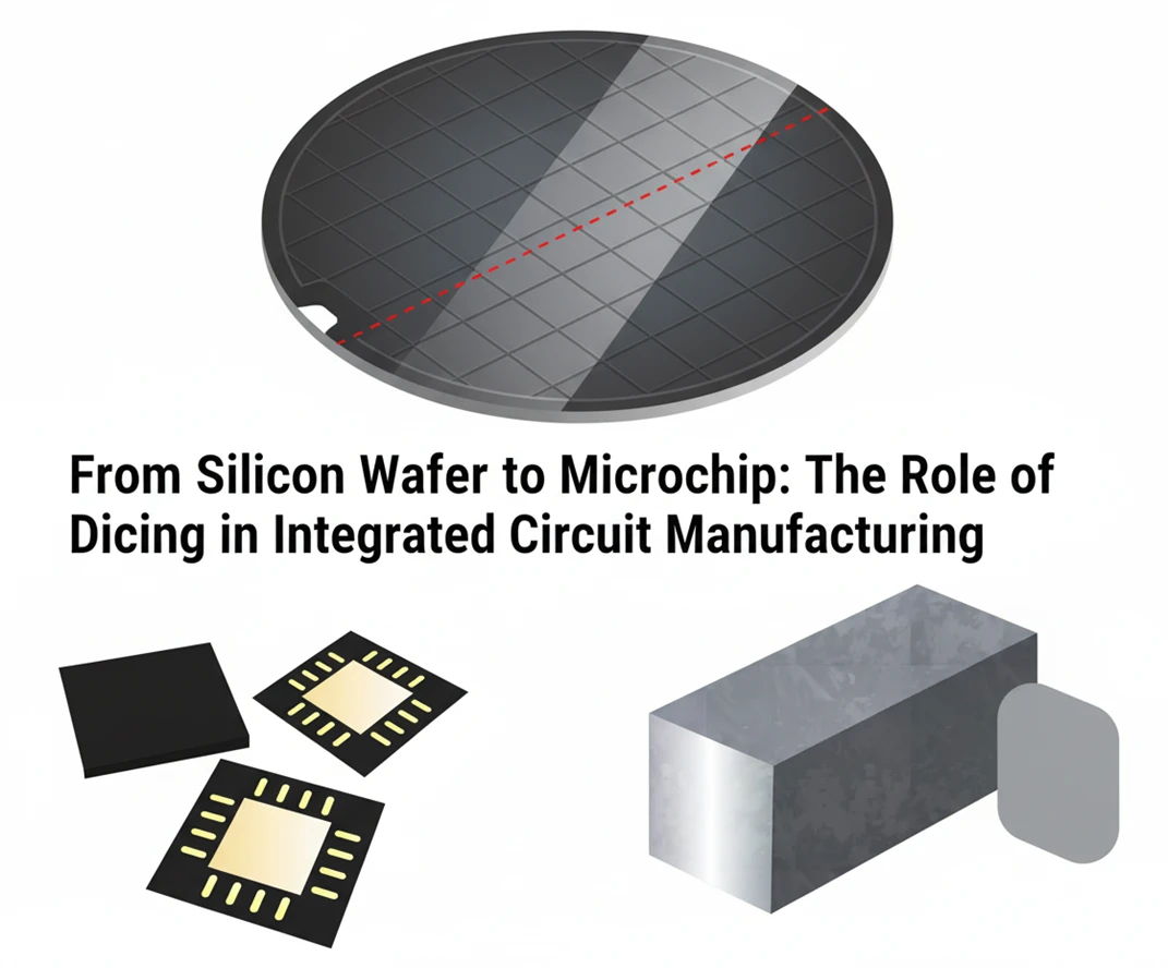
From Silicon Wafer to Microchip: The Role of Dicing in Integrated Circuit Manufacturing
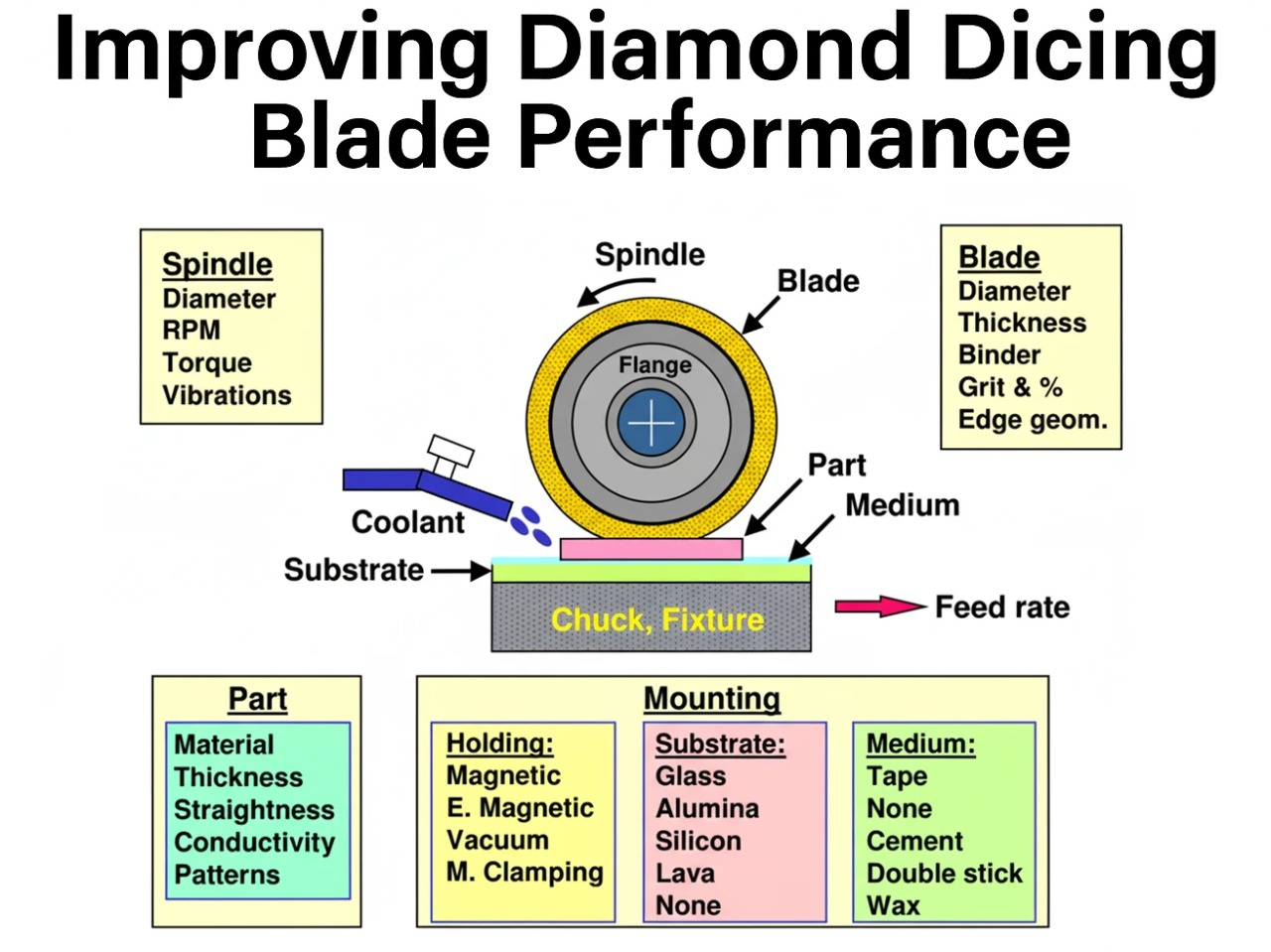
Improving Diamond Dicing Blade Performance: Key Factors and Strategies

How to Selecting Right Diamond Tools for your application

How to properly use Diamond Tools

Why use diamond
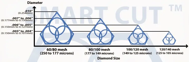
What is Diamond Mesh Size and how to select best one for your application

What is Diamond Concentration and which to use for your application

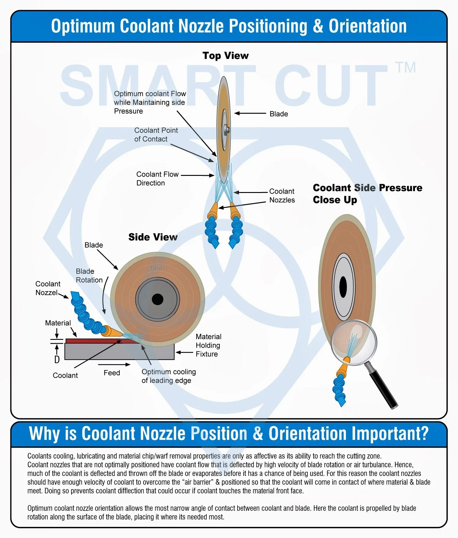
Diamond Tool Coolants Why, How, When & Where to Use

Diamond vs CBN (cubic boron nitride) Tools

Choosing The Correct Diamond Bond Type

Selecting the Right Coolant Method for your Diamond & CBN Tools
Alexander Schneider is a senior applications engineer and leading authority in the industrial diamond tooling industry, with over 35 years of hands-on experience in the development, application, and optimization of ultra-thin and high-precision diamond blades, diamond core drills, and diamond and CBN grinding wheels. His work spans a wide range of advanced materials including ceramics, glass, composites, semiconductors, and high-performance metals.
Throughout his career, he has collaborated with leading R&D institutions, national laboratories, and high-tech manufacturing companies across Europe, North America, and Asia, providing technical expertise and tailored solutions for demanding cutting and surface preparation applications.
Mr. Schneider has played a pivotal role in advancing precision cutting, sectioning, dicing, and grinding technologies used in research, production, and failure analysis. He is widely respected for his ability to optimize tool design and cutting parameters to meet exacting industry standards—balancing factors such as cut quality, blade life, material integrity, and process consistency.
As an author, Mr. Schneider is known for delivering practical, application-focused insights that translate complex technical challenges into clear, actionable strategies. His articles and technical guides serve as trusted resources for engineers, researchers, and manufacturers seeking to improve precision, reduce process variability, and enhance tool performance in critical applications.